Are you confused by the many technical terms for vibration damping, such as damping coefficient, damping constant, and damping ratio?
Damping is a fundamental concept in vibration control and an important topic that cannot be avoided in understanding vibration. This article organizes various terms related to damping in an easy-to-understand manner and provides a thorough explanation of its fundamentals.
Vibration Damping
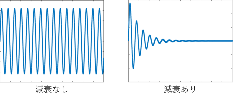
Even if an external force is applied to an object and it begins to vibrate, the vibration will not continue forever. In fact, due to various resistances such as air resistance, friction, and conversion to heat, the amplitude of the vibration decreases over time and eventually comes to rest.
This phenomenon, in which the amplitude decreases with time, is called damping. In an ideal vibrating system, vibration continues forever even when the input is lost, but in nature, damping always occurs and vibration always tends toward convergence.
Attenuation magnitude expressions and terminology
First, Table 1 summarizes the important terms used to describe the magnitude of attenuation in an organized manner.
When describing the effects of damping, a commonly used model is viscous damping, in which the resistance force is proportional to the velocity. This viscous damping is the basis for a simple treatment of many vibration phenomena.
In the commentary that follows, we will use this viscous damping as an example for more specific explanations.
Table 1 List of Attenuation Terms
| terminology | symbol | unit | Description. |
|---|---|---|---|
| damping force | fd | [N] | A force that provides resistance to vibration. In the case of viscous damping, it is proportional to the velocity of the vibration. fd=cv fdDamping force [N] c: Damping coefficient [N/m/s]. v: Velocity [m/s]. The coefficient c on the velocity is the "damping coefficient," which expresses the degree of force to resist vibration. |
| attenuation coefficient | c | [N/m/s]. | |
| attenuation ratio | zeta | [None] | It is one of the most important indicators for understanding the degree of attenuation. Ratio of actual damping factor c divided by critical damping factor cc (ζ = c/c)cThe value is represented by a number (0 to 1, or 0% to 100%). This value ranges from 0 to 1 (or 0% to 100%). In other words, the closer the damping ratio approaches 1, the faster the vibration converges. |
| decay constant | indecent | [None] | Same as damping ratio. It is often used in the field of architecture. |
Damping ratios for building structures: guidelines for each structure type
The damping ratio of a building structure is difficult to determine accurately because it is highly dependent on the materials and properties of the structure, as well as environmental conditions such as temperature, a characteristic that makes it prone to variation.
Therefore, in design and analysis, guideline values based on measured data and experimental results are used. The general guidelines for each structure type are as follows
Table 2: Approximate damping ratios for each structure type and commonly adopted values
| Structure Type | Approximate damping ratio (ζ) | General Adoption Values |
| Steel Construction (S) | 0.01∼0.02 (1% ∼ 2%) | 0.02 (2%) |
| RC (Reinforced Concrete) | About 0.03 (3%) | 0.03 (3%) |
Relationship between Damping Ratio and Vibration: Free Vibration vs. Steady-State Vibration
Free vibration (vibration after input is lost)
As shown in Figure 2,attenuation ratio depending on the value of (ζ).free vibrationwaveform varies.
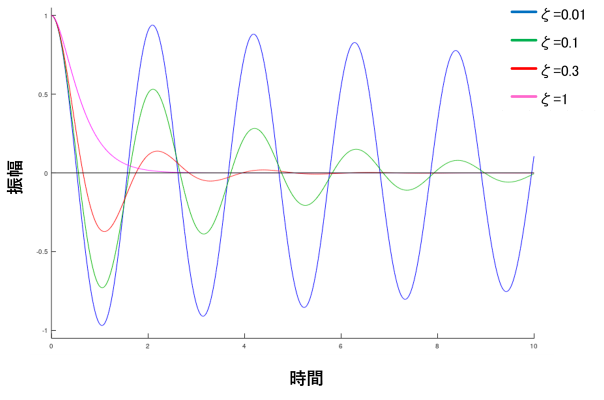
Table 3 Time to convergence and behavior for each attenuation ratio
| Attenuation ratio (ζ) | condition | Time to convergence and behavior |
| Small (ζ<1) | underdamping | Vibration continues for a long time after time (slow convergence) |
| ζ=1 | critical decay | Stands still in the shortest time without oscillation (fastest convergence) |
| Large (ζ>1) | overdecay | Converges without oscillation, but takes longer than critical decay |
(2) Steady-state vibration (external force continues to be applied)
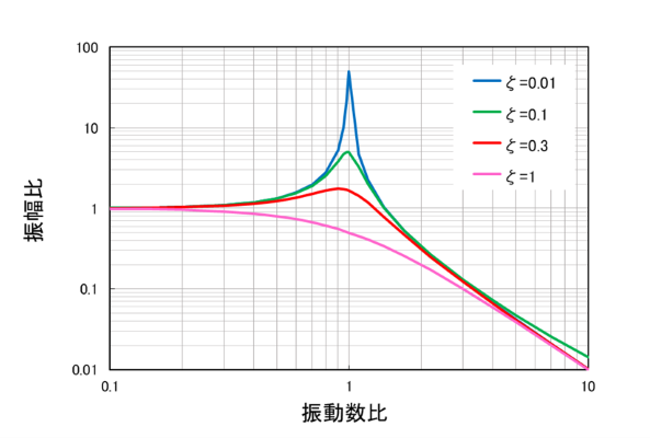
Figure 3 shows the effect of damping ratio on steady-state vibration.
Horizontal axis (frequency ratio): Ratio of frequency of input to natural frequency
Vertical axis (amplitude ratio): amplification ratio of vibration to input force
The height of the peak when the horizontal axis of the graph is 1,resonanceThis represents the vibration amplification when the
This shows that the smaller the damping ratio (ζ), the sharper the peak at resonance and the greater the amplification due to resonance. In other words, the smaller the damping ratio, the greater the risk of large vibration due to resonance.
Vibration DampingA device to increase thedamperTypes and Mechanisms of
Devices used to intentionally increase the damping of vibrations are called "dampers. Dampers are classified into various types according to the way they generate damping force.
This section introduces the typical types of dampers and their basic mechanisms in vibration control.
Table 4 Typical Damper Types and Their Basic Mechanisms
| type | Damping force generation method | Characteristics / Resistance used |
| viscous damper | Utilizes the viscous resistance of fluids such as liquids and gases | Resistance force is proportional to velocity (corresponding to viscous damping) |
| Friction Damper | Utilizes frictional resistance due to sliding motion of metals, polymer materials, etc. | Constant resistance (independent of speed) |
| History Damper | Utilizes the historical characteristics of repeated plastic deformation of metallic materials, etc. | Absorption of material deformation energy |
| mass damper | Utilizes the inertial reaction force of a movable weight (mass) attached to the vibration system | Suppress vibration by shifting natural frequencies (e.g., TMD) |
Case Studies

Example of wind sway countermeasure

Example of stair climbing vibration countermeasures